



Truck Crane Composition and How Its Systems Work
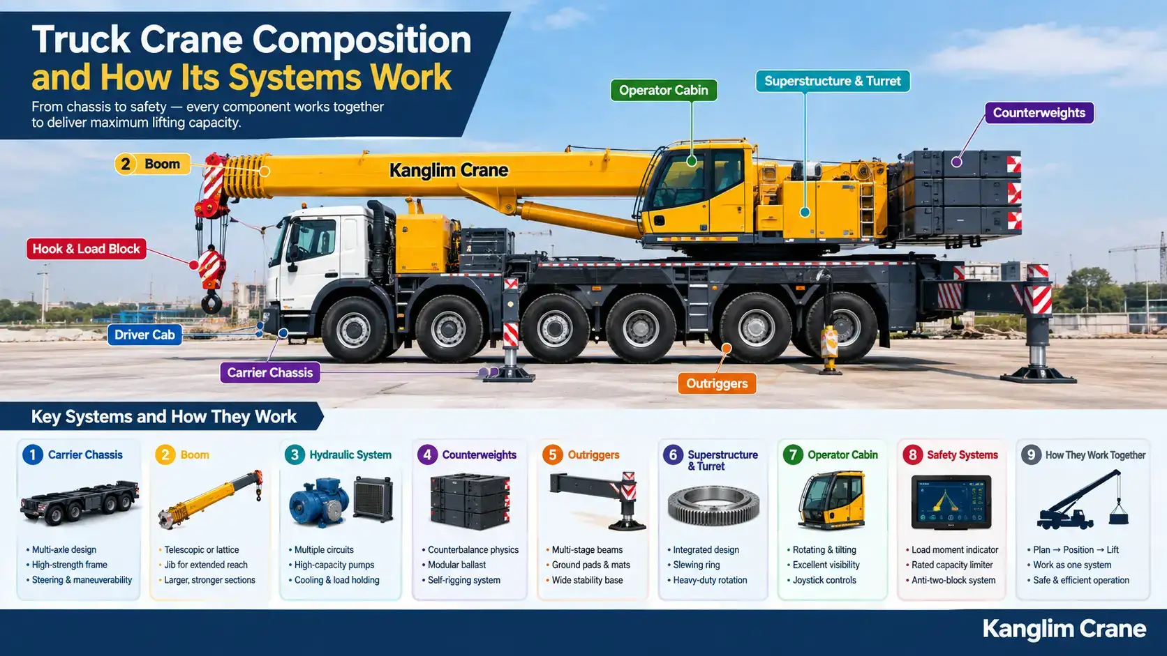
A truck crane and a boom truck can look similar from across a job site, both mounted on wheels with a large hydraulic arm rising from behind the cab. Underneath that surface resemblance, the two machines share almost none of the same structural logic. A truck crane is not a larger boom truck. It is a different machine built around a different priority: producing maximum lifting capacity from a mobile platform, with every other consideration, including cargo space, road simplicity, and setup speed, deliberately traded away to get there.
This guide breaks the machine down system by system, carrier chassis, boom, hydraulics, counterweights, outriggers, superstructure, operator cabin, and safety monitoring, and explains what each component does and how it works. Buyers evaluating truck mounted cranes often ask exactly these questions, since understanding the machine's construction is what separates an informed purchase from one based on a tonnage figure alone.
01. The Carrier Chassis: Purpose-Built, Not Adapted
Everything about how a truck crane performs starts with the chassis it is built on, and this is the first point where it departs completely from a boom truck.
1.1 Custom Multi-Axle Carrier Design
A boom truck begins life as a standard commercial truck chassis, purchased from a truck manufacturer and then reinforced where the crane mounts. A truck crane begins as a purpose-engineered carrier, designed from the ground up for one job: supporting a crane superstructure. There is no donor truck underneath it.
This carrier typically runs three, four, or more axles depending on the machine's rated capacity, spaced along a longer frame than any standard commercial truck would use. The frame itself is built from thicker, higher-grade structural steel throughout, not just at reinforced sections, because the entire length of the chassis participates in resisting the bending and torsional forces a heavy lift generates.
1.2 Why Axle Count and Spacing Matter at This Scale
Every road and bridge has a maximum load rating, and those ratings are typically expressed per axle rather than per vehicle. A machine weighing considerably more than a standard truck can still travel legally on many routes if that weight is distributed across enough axles that no single axle exceeds its permitted load.
This is why axle count scales with machine capacity. It is not simply about holding the weight up, which a smaller number of heavier-rated axles could technically do. It is about spreading that weight so the machine remains transportable without exceeding per-axle limits, and so it does not sink into or damage the ground surface it parks on at a job site.
1.3 Steering and Maneuverability Systems
Because a multi-axle carrier is considerably longer than a standard truck, many truck cranes include multi-axle steering, where rear axles steer in coordination with the front axles rather than simply following. This reduces the machine's effective turning radius, which would otherwise be impractically wide for a vehicle of that length, and allows crab steering on some models, where all axles turn in the same direction to move the machine sideways into a tight position.
02. The Boom: Telescopic and Lattice Configurations
The boom is where a truck crane's reach and capacity are physically realized, and at this scale, two distinct design approaches are used depending on the application.
2.1 Telescopic Booms at Truck Crane Scale
Most truck cranes use a telescopic boom, built on the same nesting principle as a boom truck's boom but at significantly larger dimensions. Sections are longer, wall thicknesses are greater, and the hydraulic cylinders driving extension are correspondingly larger.
The engineering challenge grows disproportionately with size. A longer boom means a longer lever arm, which means the same load produces a much larger bending moment at the boom's base. This is why boom sections on larger machines use progressively more sophisticated cross-sectional shapes, often hexagonal or oval rather than simple rectangular, since these shapes resist bending and twisting more efficiently for a given amount of steel.
2.2 Lattice Boom Sections
On the largest truck cranes, a lattice boom replaces or supplements the telescopic design. A lattice boom is an open framework of steel tubes and struts, welded into a rigid truss structure, rather than a solid-walled box section.
The advantage is weight. A lattice structure achieves comparable rigidity to a solid section using substantially less steel, because the truss geometry distributes forces along its members rather than relying on wall thickness. Less boom weight means more of the machine's rated capacity is available for the actual load rather than being consumed by lifting the boom itself, which becomes the dominant consideration at extreme reach.
The trade-off is assembly. A lattice boom does not telescope. Sections are transported separately and assembled on site, which adds significant setup time and makes the machine impractical for anything except long-duration projects where that setup cost is amortized across weeks or months of work.
2.3 Jib Attachments and Extended Reach
Many truck cranes accept a jib, a secondary boom section attached to the tip of the main boom that extends reach further, usually at a fixed offset angle. Jibs dramatically increase maximum height but sharply reduce available capacity, since they add both length to the lever arm and weight at the furthest point from the machine's center. They are used specifically when height matters more than tonnage, such as placing a light component at the top of a tall structure.
03. The Hydraulic System: Scaled for Sustained Heavy Cycles
The hydraulic system on a truck crane operates under fundamentally different demands than the equivalent system on lighter equipment.
3.1 Pump Capacity and Multiple Circuits
Where a boom truck typically runs a single hydraulic pump serving all functions, a truck crane often uses multiple pumps or a single high-capacity pump feeding separate hydraulic circuits. Separating circuits allows the machine to perform multiple functions simultaneously, such as raising the boom while rotating the turret, without one function starving the other of hydraulic flow.
Pump capacity at this scale is driven not just by peak force requirements but by cycle duration. A machine performing sustained lifting operations over an entire work shift generates significantly more heat in its hydraulic fluid than one performing occasional short lifts, which affects both pump sizing and the cooling capacity built into the system.
3.2 Hydraulic Fluid Cooling
Because sustained heavy operation generates continuous heat, truck cranes include dedicated hydraulic fluid coolers, typically air-to-oil heat exchangers with their own fans. Hydraulic fluid that overheats loses viscosity, which reduces the system's ability to maintain pressure and accelerates wear on pumps, seals, and valves. Cooling capacity is therefore a genuine performance specification at this scale rather than an afterthought.
3.3 Load Holding Under Extended Duration
Load holding valves on a truck crane must maintain a suspended load safely for far longer periods than lighter equipment typically requires, since positioning a heavy component precisely can take considerable time. These valves are engineered with tighter tolerances and redundant sealing to prevent even minimal drift over extended holds, since a slow downward creep that would be negligible on a light load becomes a serious hazard when the suspended weight is measured in tons.
04. Counterweights: How They Enable Higher Capacity
Counterweights are the single most visible component on a truck crane that has no equivalent on a boom truck, and they are central to how the machine achieves its rated capacity.
4.1 The Physics of Counterbalance
When a crane lifts a load at a distance from its center of rotation, that load creates a tipping moment, the product of the load's weight and its horizontal distance from the tipping point. To lift safely, the machine must generate a larger opposing moment in the other direction.
A boom truck generates this opposing moment almost entirely from its own chassis weight and outrigger spread. A truck crane adds counterweights, dense steel or concrete blocks positioned at the rear of the rotating superstructure, specifically to increase this opposing moment. Because these weights sit at a distance behind the center of rotation, each ton of counterweight contributes far more resisting moment than a ton of additional chassis weight would.
4.2 Modular Ballast Systems
Counterweights are almost always modular, made up of individual slabs that stack and lock together, rather than a single fixed mass. This modularity exists because counterweight requirements vary by job. A lift requiring maximum capacity at long reach needs full counterweight, while a lighter job may need only partial ballast.
Modularity also solves a transport problem. A fully ballasted truck crane would exceed road weight limits on most routes, so counterweights are frequently transported separately on a support truck and installed at the job site.
4.3 Self-Rigging Systems
Many modern truck cranes include a self-rigging capability, using the machine's own hydraulic systems to lift counterweight slabs from a transport vehicle and position them onto the superstructure without requiring a second crane. This meaningfully reduces setup cost and complexity, since the alternative, bringing an additional crane to assemble the primary crane, is both expensive and logistically demanding.
05. Outriggers: Wider Bases for Larger Loads
Outriggers perform the same conceptual function on a truck crane as on any lifting machine, but their construction and deployment differ substantially at this scale.
5.1 Multi-Stage Outrigger Beams
Outrigger beams on a truck crane typically extend in multiple stages, telescoping outward in sequence to reach a spread considerably wider than the machine's body. This multi-stage design allows the machine to achieve a wide stability base when fully deployed while still retracting into a legal transport width.
Many machines also support partial outrigger deployment, where beams extend to an intermediate position rather than full spread. This is necessary on constrained job sites, and the machine's load chart accounts for it, listing reduced capacities for each partial deployment configuration.
5.2 Ground-Bearing Pressure and Pad Sizing
The forces transmitted through an outrigger on a heavy lift are substantial, concentrated into a small contact area. Ground-bearing pads spread this force across a larger surface, and at truck crane scale, pads alone are frequently insufficient. Operators commonly place additional cribbing, timber mats or engineered steel plates, beneath the pads to distribute force further.
Calculating whether ground conditions can support the resulting pressure is a genuine engineering step before a heavy lift, not a formality. Ground failure beneath an outrigger during a lift is among the more serious failure modes for this equipment.
06. The Superstructure and Turret: Integrated Design
The superstructure is the rotating upper portion of the machine, carrying the boom, the operator cabin, the counterweights, and much of the hydraulic and control machinery.
6.1 Factory-Integrated Construction
On a boom truck, the crane assembly is a separate unit bolted onto a truck chassis, with hydraulic and power connections linking the two. On a truck crane, the superstructure and carrier are engineered together as a single machine from the outset. The turret bearing, the large-diameter slewing ring that allows the superstructure to rotate, is a structural component of the machine rather than an interface between two separately manufactured assemblies.
This integration is what allows the machine to transmit lifting forces efficiently from the boom, through the superstructure, across the slewing ring, and into the carrier chassis, without the stress concentrations that a bolted interface would create at these load levels.
6.2 Slewing Ring and Rotation Mechanics
The slewing ring is a large ball or roller bearing assembly with gear teeth machined into one of its races. A hydraulic motor drives a pinion gear that engages these teeth, rotating the superstructure. Because this single bearing carries the entire vertical load, overturning moment, and rotational force of every lift, it is among the most critical and heavily engineered components on the machine.
Rotation speed is deliberately slow and heavily damped. A suspended load has considerable momentum, and rapid acceleration or deceleration of rotation would cause the load to swing, creating dynamic forces well beyond the static weight the machine is rated for.
07. The Operator Cabin: Independent and Rotating
Where a boom truck operator typically works from the truck cab or a basic swing seat, a truck crane provides a dedicated operating environment.
7.1 Dedicated Upper Cabin
The operator cabin on a truck crane is a separate enclosed station mounted on the rotating superstructure, distinct from the driving cab on the carrier. It rotates with the boom, so the operator's orientation relative to the load never changes regardless of which direction the machine is slewed.
Most cabins also tilt backward, allowing the operator to look upward along the boom during high lifts without straining, which matters over the course of a long shift performing repeated high-elevation placements.
7.2 Visibility and Working Environment
Cabin design prioritizes sightlines, with large glazed areas including overhead skylights giving direct visual contact with the load throughout its travel. Climate control is standard rather than optional, since operators may spend an entire shift in the cabin, and heat or cold-induced fatigue directly affects the precision and judgment a heavy lift requires.
7.3 Control Interfaces
Controls are typically joystick-based, with proportional response so that the degree of stick movement corresponds to the speed of the resulting function. Alongside the physical controls, a display presents real-time data from the load monitoring system, giving the operator continuous feedback on current load, boom angle, radius, and remaining capacity.
08. Safety Systems: Load Monitoring at Scale
Safety systems on a truck crane perform the same function as on lighter equipment but carry proportionally greater consequences, which shapes how they are designed.
8.1 Load Moment Indicators and Rated Capacity Limiters
A load moment indicator continuously calculates the machine's current load moment from sensor data, boom angle, boom length, and load weight derived from hydraulic pressure, and compares it against the programmed load chart for the machine's current configuration.
At truck crane scale, these systems typically go beyond warning. A rated capacity limiter actively prevents the operator from initiating movements that would exceed safe limits, cutting hydraulic function in the direction that would increase load moment rather than relying solely on the operator responding to an alarm.
8.2 Configuration-Dependent Load Charts
A truck crane does not have one load chart. It has many, each corresponding to a specific configuration: counterweight installed, outrigger spread, boom length, whether a jib is fitted, and whether the lift is over the front, side, or rear of the machine. Capacity varies substantially between these configurations.
The load monitoring system must be told which configuration is currently set up, and an incorrectly configured system will calculate capacity against the wrong chart. Configuration verification before a lift is therefore a genuine safety-critical step rather than a procedural box to tick.
8.3 Anti-Two-Block Systems
An anti-two-block system prevents the hook block from being drawn up into the boom tip sheave, a condition that can sever the hoist rope and drop the load. A weight-and-switch assembly at the boom tip detects the hook approaching and automatically stops the hoist function. This is standard equipment at this scale, since the consequences of a two-block event with a heavy suspended load are severe.
09. How These Systems Work Together During a Lift
Each system covered above operates as part of a sequence, and understanding that sequence shows how they depend on one another.
9.1 Site Preparation and Positioning
Before the machine arrives, the lift is planned: load weight confirmed, required radius measured, ground conditions assessed, and the necessary configuration determined from the load charts. The machine is then positioned, accounting for the space required for full outrigger deployment and superstructure rotation.
9.2 Outrigger Deployment and Leveling
Outriggers extend to the planned spread, cribbing is placed where ground conditions require it, and the machine is leveled precisely. Level accuracy directly affects load moment calculations, since an out-of-level machine shifts its own center of gravity in a way the monitoring system's calculations assume it has not.
9.3 Counterweight Installation
Counterweight slabs are installed to the configuration the lift plan specifies, typically using the machine's self-rigging system. The load monitoring system is then configured to reflect the installed counterweight, since capacity calculations depend directly on it.
9.4 Boom Assembly or Extension
A telescopic machine extends its boom to the planned length. A lattice machine assembles boom sections on the ground and raises the completed boom, a process that can take considerably longer and may require an assist crane depending on configuration.
9.5 The Lift and Placement
With the machine configured and verified, the load is rigged and lifted. The operator manages hoist, boom angle, and slew together to move the load along its planned path, working within the limits the load monitoring system displays continuously. Rotation is deliberately gradual to avoid inducing swing in the suspended load.
9.6 Stow and Demobilization
After placement, the sequence reverses: boom retracted or disassembled, counterweights removed for transport, outriggers retracted, and the machine returned to travel configuration. On a machine requiring separate counterweight and boom transport, demobilization is a genuine logistical operation rather than a matter of driving away.
What This Composition Tells a Buyer
Understanding how a truck crane is built explains why its specifications behave the way they do. Capacity is not a single number but a function of counterweight, outrigger spread, boom configuration, and load position. Setup time is longer because ballast installation and precise leveling are structural requirements, not optional refinements. Transport is more complex because the machine's fully configured weight is deliberately higher than what any single road permit would allow.
None of these characteristics are drawbacks of the design. They are the direct consequences of engineering a mobile machine for lifting capacity that a simpler platform cannot reach, and recognizing that trade-off is what allows a buyer to judge whether this class of equipment genuinely matches the work in front of them.
Get the Full Configuration Breakdown for Your Lift Requirements
Load charts, counterweight options, boom configurations, and outrigger requirements all interact, and the right combination depends on the specific lifts a machine will be doing rather than a general capacity figure. Kanglim Crane is an established truck mounted cranes manufacturer, producing this equipment and shipping it to buyers across multiple regions, so your team gets the same configuration support whether you are sourcing locally or arranging delivery from overseas. We can walk your team through the exact configuration options behind any unit in our range, including how capacity shifts across different setups.
Share the lift requirements you are planning around, and we will provide the configuration detail your engineers need to confirm the right machine before an order is placed.
Featured Articles
A truck crane and a boom truck can look similar from across a job site, both mounted on wheels wi
READ FULLA boom truck looks straightforward from the outside: a
READ FULLSmall, occasional lifts are exactly the kind of work that makes renting feel like the obvious cho
READ FULL