



Telescopic Boom Truck Composition and How Every Part Works
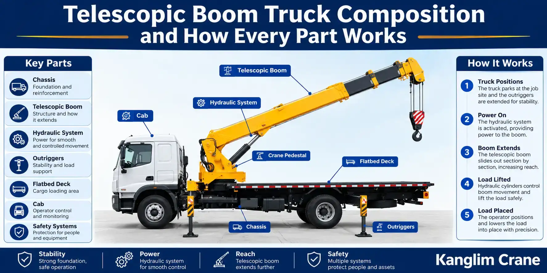
A boom truck looks straightforward from the outside: a truck chassis with a crane arm mounted behind the cab. What actually happens inside that machine, from the moment it parks on a job site to the moment it lifts a load into place, involves several distinct systems working together in a specific sequence. Most buyers evaluate this equipment by tonnage and price alone, without understanding what physically produces those numbers or what actually fails when a machine underperforms its rated specifications.
This guide breaks the machine down into its core components, chassis, boom, hydraulic system, outriggers, flatbed deck, cab, and safety systems, and explains how each one works on its own and how they function together during an actual lift. The goal is a genuine working knowledge of the equipment, not a spec sheet summary. Buyers sourcing equipment from a China boom trucks factory for the first time often ask detailed questions about exactly these systems, and this guide covers the answers in full rather than in the abbreviated form found on most product pages.
01. The Chassis: Foundation and Reinforcement
Every other system on this equipment depends on the chassis to hold it in place, transmit load forces safely to the ground, and keep the truck stable both during transit and during a lift. Understanding chassis construction explains why heavier-rated machines cost more and weigh more, and why a lighter machine cannot simply be "upgraded" to lift more without structural changes throughout the frame.
1.1 Frame Construction and Materials
The chassis begins as a steel frame, typically built from high-strength low-alloy steel selected for its strength-to-weight ratio. Two main rails run the length of the truck, connected by cross members at intervals that add rigidity and prevent the frame from twisting under load. On a standard commercial truck, this frame is optimized purely for road use and cargo weight distribution. On a boom truck, engineers add reinforcement to specific sections of this frame, particularly around the area where the crane pedestal mounts, since this is where concentrated stress from lifting operations gets transmitted into the chassis.
The steel gauge, or thickness, used in these reinforced sections scales directly with the tonnage the machine is rated to lift. A frame built for lighter, occasional lifts uses thinner reinforcement than a frame built for sustained heavy lifting, since the forces each must absorb differ substantially.
1.2 Mounting Points and Load Transfer
The crane superstructure bolts or welds onto the chassis at specific mounting points, usually reinforced with additional steel plates called doubler plates. These mounting points are engineering-critical, since they are where the entire force of a lift, including the weight of the load, the boom, and any dynamic forces from movement, gets transferred from the crane assembly into the truck frame.
Poorly designed or under-reinforced mounting points are a common failure point on lower-quality equipment, since repeated stress cycles at these connections can eventually cause fatigue cracking. Properly engineered mounting points distribute this stress across a wider area of the frame rather than concentrating it at a single connection.
1.3 How Chassis Reinforcement Scales Across Tiers
At the lighter end of the lineup, a mini boom crane truck uses a chassis with modest reinforcement, since its rated tonnage and boom length place comparatively low stress on the frame. This lighter chassis is part of what keeps the machine's overall weight down, which in turn supports its compact footprint and easier maneuverability. As tonnage rises through the lineup, chassis reinforcement increases correspondingly, with thicker steel, additional cross members, and reinforced mounting points designed to handle the greater torsional stress that comes with a longer boom and higher rated capacity.
02. The Telescopic Boom: Structure and How It Extends
The boom is the component most people associate with this equipment, and its design determines both how far the machine can reach and how much weight it can lift at that reach. Understanding how a telescopic boom physically extends explains both its strengths and its limitations compared to other boom designs.
2.1 Nested Boom Sections
A telescopic boom consists of multiple hollow steel sections nested inside one another, similar in concept to a collapsible car antenna but built from structural steel rather than thin metal tubing. The largest section, called the base section, is fixed to the crane's rotating turret. Each subsequent section is slightly smaller in cross-section, allowing it to slide inside the section before it.
The number of sections varies by model and tier, with lighter machines typically using fewer, shorter sections, and heavier machines using more sections to achieve greater maximum reach while still retracting into a manageable stowed length for road transport.
2.2 Hydraulic Cylinder-Driven Extension
Extension and retraction are driven by hydraulic cylinders mounted inside the boom assembly. In a common configuration, a base cylinder extends the second section directly, and a system of internal cables and pulleys, sometimes called a cable-reeving system, synchronizes the extension of additional sections so they move in sequence rather than independently. This synchronization matters because uneven extension between sections would create instability and uneven stress distribution across the boom structure.
Some designs use a separate hydraulic cylinder for each section rather than a cable-reeving system, which adds mechanical complexity but can offer more precise independent control over each section's extension.
2.3 Wear Pads and Section Alignment
Between each nested section sits a series of wear pads, typically made from a low-friction composite material, that keep the sections aligned as they slide against one another and prevent metal-on-metal contact that would cause rapid wear and damage. These pads absorb friction during extension and retraction and require periodic inspection, since excessive wear here creates side-to-side play in the boom that affects both precision and structural integrity under load.
2.4 How Boom Reach Scales Across Tiers
A light duty boom truck uses a boom with a moderate number of sections, offering more reach than the smallest tier in the lineup while keeping the stowed length manageable for standard road transport and quick job-site setup. As tonnage and intended application shift toward heavier commercial work, boom length and section count increase, extending maximum reach further, though always within limits set by what the chassis and hydraulic system underneath can safely support at full extension.
03. The Hydraulic System: Pump, Cylinders, and Valves
If the boom is the visible reach of the machine, the hydraulic system is what actually generates the force behind every movement, from boom extension to load lifting to outrigger deployment. This system converts mechanical power from the truck's engine into controlled hydraulic force.
3.1 How the Pump Generates Flow and Pressure
A hydraulic pump, typically driven by a power take-off unit connected to the truck's engine, draws hydraulic fluid from a reservoir and pressurizes it. This pump generates flow, measured in gallons per minute, and pressure, measured in pounds per square inch. Flow determines how quickly a hydraulic function can move, while pressure determines how much force that function can exert against resistance, such as the weight of a load.
The pump's rated capacity is one of the most important specifications on the entire machine, since every hydraulic function on the truck, boom extension, lifting cylinder movement, outrigger deployment, and boom rotation, draws from this same pressurized fluid supply.
3.2 Cylinders and Control Valves
Hydraulic cylinders convert pressurized fluid into mechanical movement. A cylinder consists of a piston inside a sealed tube, and directing pressurized fluid to one side of the piston versus the other extends or retracts the cylinder rod, which in turn moves whatever mechanical component that cylinder is connected to, whether that is the boom's lift angle, its telescopic extension, or an outrigger leg.
Control valves regulate where hydraulic fluid flows at any given moment, allowing the operator to direct pressurized fluid to specific cylinders through joystick or lever controls in the cab. These valves also allow the operator to hold a cylinder in a fixed position, which is what keeps a load suspended at a stable height rather than drifting once the operator releases the control input.
3.3 Load Holding and Relief Valves
A critical safety component within this system is the relief valve, which prevents hydraulic pressure from exceeding safe limits by diverting excess pressure back to the reservoir rather than allowing it to build to a point that could rupture a hose or damage a component. Load holding valves, sometimes called counterbalance valves, prevent a cylinder from retracting under load even if hydraulic pressure momentarily drops, which is what stops a suspended load from suddenly falling if a hose were to fail.
3.4 How Hydraulic Capacity Scales Across Tiers
A medium duty boom truck uses a larger pump and correspondingly sized cylinders than a lighter tier, delivering the additional flow and pressure needed to move a heavier boom assembly and lift its rated tonnage at a reasonable speed. Undersized hydraulic components relative to a machine's rated capacity would result in sluggish boom movement and reduced lifting speed under load, even if the structural components were rated for the higher tonnage, which is why pump and cylinder sizing must scale in step with every other system on the truck.
04. Outriggers: How the Truck Stays Stable During a Lift
A truck's standard tires and suspension are not designed to handle the lateral and tipping forces generated by lifting a heavy load at extended reach. Outriggers solve this problem by creating a wider, more stable base than the truck's wheelbase alone can provide.
4.1 Deployment Mechanism
Outriggers are hydraulically actuated arms, typically mounted near the front and rear of the chassis, that extend horizontally outward from the truck body and then vertically downward until a pad at the end of each leg contacts the ground and lifts the truck's tires slightly off the surface. This horizontal-then-vertical extension sequence widens the machine's effective footprint well beyond its actual body width, which is what allows it to resist tipping forces during a lift that its wheelbase alone could never withstand.
4.2 Ground-Bearing Pads and Load Distribution
At the base of each outrigger leg sits a ground-bearing pad, a flat plate that spreads the concentrated force from that single outrigger leg across a wider area of ground contact. Without this pad, the force at a single point could exceed the ground's bearing capacity, causing the outrigger to sink, particularly on soft or uneven surfaces. On some setups, additional wooden or steel cribbing is placed under the pads to further distribute load on marginal ground conditions.
4.3 The Physics of Stability
Stability during a lift comes down to a straightforward physical principle: the combined weight of the truck and any counterweight must create enough resisting moment to offset the tipping moment created by the load at whatever boom angle and extension it is being lifted at. A wider outrigger stance increases the resisting moment available, which is why outrigger spread, not just outrigger strength, is a critical stability factor. This is also why load charts specify reduced capacity as boom extension increases, since a longer lever arm increases the tipping moment for the same load weight.
4.4 How Outrigger Design Scales Across Tiers
At the top of the boom truck lineup, heavy lifting boom trucks use outriggers with a wider maximum spread and larger ground-bearing pads than lighter tiers, since the tipping forces generated by heavier loads at longer boom extensions require a proportionally larger stable base to resist safely. Lighter tiers use a more compact outrigger footprint, which keeps overall job-site space requirements lower but limits the maximum stable lifting capacity available at that tier.
05. The Flatbed Deck: Dual-Purpose Cargo and Lift Capability
What separates a boom truck from a dedicated truck-mounted crane is not the crane mechanism itself but the flatbed deck built into the same chassis, giving the machine a second function beyond lifting.
5.1 Deck Construction and Chassis Integration
The flatbed deck sits behind the cab and, on most configurations, behind or around the base of the crane pedestal, built from structural steel plate or, on some models, a combination of steel framing with a wood or composite deck surface. This deck is mounted directly to the chassis frame, sharing the same structural foundation as the crane mounting points, which means deck load capacity and crane mounting strength are engineered together rather than as independent systems.
5.2 Why This Shared Design Defines the Equipment Category
This dual-purpose design is the defining structural characteristic of a boom truck as a category. A crew can load materials, tools, or equipment onto the deck, drive to a job site at standard highway speeds, and then use the same vehicle's crane to unload and position those materials, without requiring a second vehicle. A dedicated truck-mounted crane sacrifices this cargo capability entirely, dedicating its full chassis to the crane apparatus in exchange for higher lifting capacity than a comparably sized boom truck could offer.
06. The Cab and Controls: Operator Interface
The cab is where the operator translates a lift plan into actual machine movement, and its design directly affects both operational efficiency and the operator's ability to see the load throughout a lift.
6.1 Fixed Cab Design
In a fixed cab configuration, the operator controls both driving and crane functions from the same cab, which does not rotate. Crane controls, typically hydraulic joysticks or levers, are integrated into this single cab alongside the truck's standard driving controls. This design keeps the machine mechanically simpler and is common on lighter tiers where crane operations are more straightforward and the operator's fixed vantage point is less often a limiting factor.
6.2 Swing Cab Design
A swing cab, by contrast, is a separate operator station, distinct from the driving cab, that physically rotates along with the crane's turret as it swings during operation. This gives the operator a continuously optimal view of the load and lift path regardless of which direction the boom is pointed, which becomes more valuable as lift complexity, boom length, and job-site obstruction increase.
6.3 Control Layout and Operator Function
Regardless of cab type, the operator's controls typically include separate inputs for boom extension and retraction, boom angle (raising and lowering), turret rotation (swinging the boom left or right), outrigger deployment, and the main hoist winch if the machine is equipped with one. Modern systems often integrate a digital display showing real-time load, angle, and extension data alongside these physical controls, giving the operator continuous feedback rather than requiring them to rely on the load chart alone.
07. Safety Systems: Load Monitoring and Real-Time Indicators
Because lifting operations involve constantly changing forces as boom angle and extension change, this equipment relies on active monitoring systems rather than static safety limits alone.
7.1 How a Load Moment Indicator Works
A load moment indicator uses sensors positioned at the boom's base and along its length to continuously measure boom angle, extension length, and the actual load being lifted, typically detected through pressure sensors in the main lift cylinder. The system calculates the current load moment, the product of load weight and effective boom radius, in real time and compares it against the machine's rated capacity at that specific angle and extension combination, drawn from the load chart programmed into the system.
If the operator approaches or exceeds a safe threshold, the system provides audible and visual warnings, and on many machines, can automatically prevent further movement in the direction that would increase the risk of tipping. This active monitoring is what allows an operator to work confidently near the edge of the machine's rated capacity without relying solely on manual calculation or a printed load chart.
7.2 Wireless Remote Controls
Many machines in this category, particularly at higher capacity tiers, offer wireless remote control as an option or standard feature, allowing the operator to step away from the cab entirely and control the crane from a position with a clearer view of the load and its landing point. This matters most during precise positioning tasks, where standing closer to the actual work area, rather than viewing it through a cab window at a distance, significantly improves accuracy and reduces the risk of a misjudged placement.
08. How It All Works Together: The Full Lift Sequence
Understanding each component individually only tells part of the story. The way these systems work together, in a specific sequence, is what actually produces a safe, controlled lift.
8.1 Setup and Positioning
The sequence begins with positioning the truck as close as practical to the load and its intended destination, accounting for the ground conditions and space needed for full outrigger deployment. The operator then engages the power take-off, which connects the truck's engine to the hydraulic pump and activates the crane's hydraulic system.
8.2 Outrigger Deployment and Leveling
Outriggers deploy next, extending horizontally and then vertically until each ground-bearing pad makes solid contact and the truck's tires lift clear of the ground. The operator confirms the machine is level, since an unlevel setup affects both the accuracy of the load moment indicator's calculations and the machine's actual stability margins during the lift.
8.3 Boom Extension and Positioning
With the machine stabilized, the operator extends and angles the boom toward the load, using the turret to rotate as needed. Throughout this phase, the load moment indicator continuously calculates the machine's remaining safe capacity based on the boom's current angle and extension, updating in real time as the operator makes adjustments.
8.4 The Lift
Once the boom is positioned and the load is rigged, the operator engages the main hoist or lift cylinder to raise the load, monitoring the load moment indicator throughout. The operator then uses turret rotation and boom angle adjustment together to move the load to its destination, working within the capacity limits the system displays at each position.
8.5 Placement and Stow
After the load is placed and released, the operator reverses the sequence: retracting the boom, lowering it to its stowed position, and retracting the outriggers before driving away. This final stow sequence matters as much as setup, since a boom or outrigger left partially extended creates both a transport hazard and unnecessary stress on components not designed to travel in an extended position.
What This Means for Evaluating a Machine
Understanding how these systems work together changes what a buyer actually looks for beyond a tonnage figure and a price. Chassis reinforcement, hydraulic capacity, outrigger spread, and boom design all need to scale together for a machine to perform safely and consistently at its rated capacity, not just on the day it leaves the factory but after years of regular use. A machine where one system is undersized relative to the others, even if the headline spec looks competitive, tends to show that weakness first under real working conditions rather than on a spec sheet.
Get Full Component Specifications Straight From the Factory
Spec sheets summarize a machine's capabilities, but they rarely explain what is actually inside it or why one unit holds up better than another under the same rated load. As an established China boom truck factory, we can walk you through the exact chassis, hydraulic, and outrigger specifications behind any unit in our lineup, so your team understands precisely what you are buying before an order is placed.
Reach out with the tier or application you are evaluating, and we will provide the full component breakdown behind it.
Featured Articles
A boom truck looks straightforward from the outside: a
READ FULLSmall, occasional lifts are exactly the kind of work that makes renting feel like the obvious cho
READ FULLBoom truck buyers often compare models by price or by
READ FULL